The ESP32-S3 MiniPro module
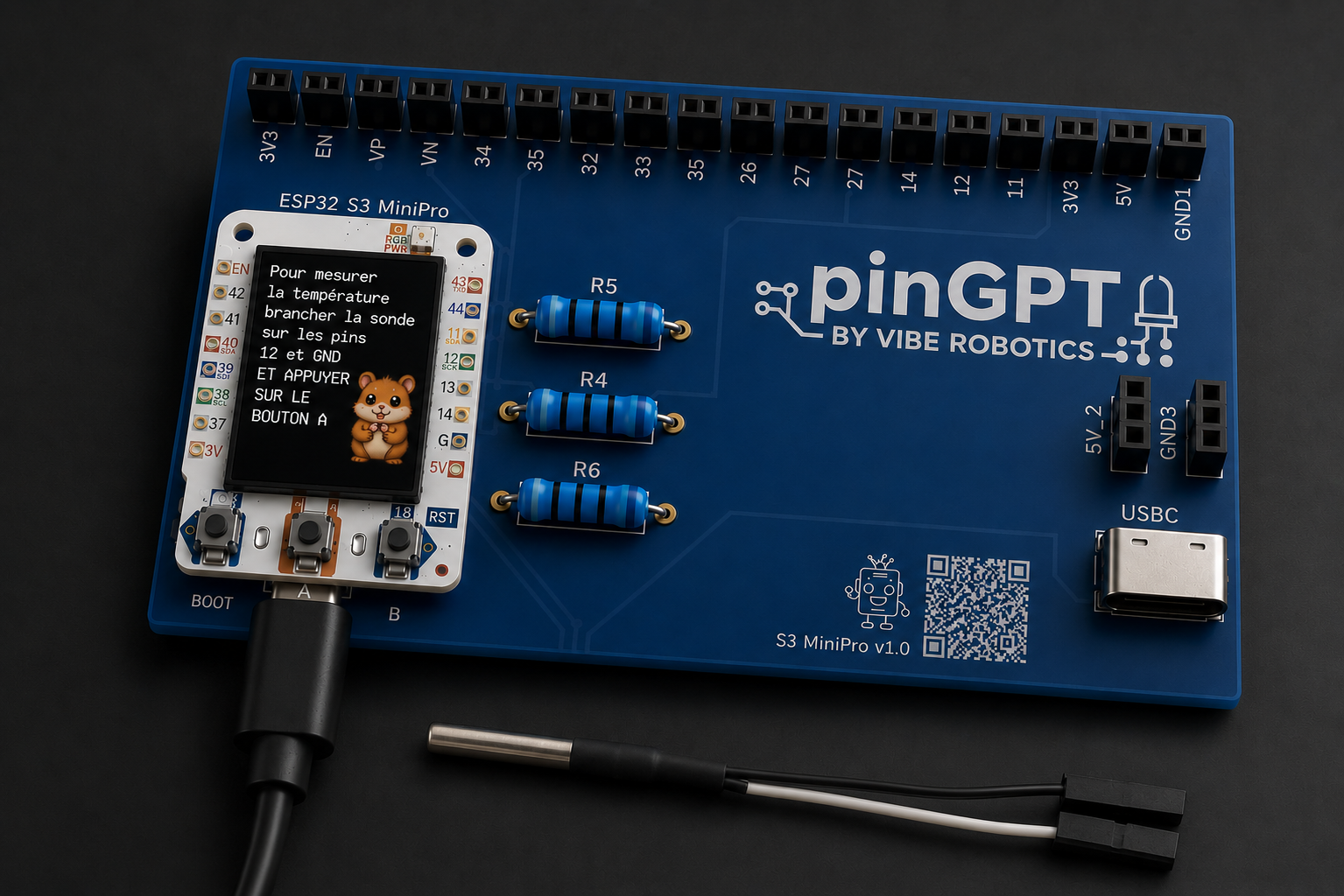
At the center of your pinGPT sits the brain: the ESP32-S3 MiniPro. It's the small black rectangle with a metal shield. This is the chip that runs your code.
GPIO pins
Around the module you'll find rows of metal pins called GPIO (General Purpose Input/Output). These are how your board talks to the world — LEDs, sensors, buttons.
Power rails: 3V3, 5V, GND
Three pins are special: 3V3 (3.3 volts), 5V (5 volts), and GND (ground). They give power to anything you connect.
The carrier board
The larger board underneath the ESP32 is the carrier board. It safely holds the ESP32 and adds extras like the second USB port for powering motors. We'll only use the ESP32's own USB port for now.
Removing and replacing the ESP32 safely
If you ever need to lift the ESP32, pull gently and evenly from both short ends — never from the antenna side. To put it back, line up every pin before pressing down.